


(this is the ‘switch’ transistor in the loopfilter section).
2.- L1 = 4.5 turns, 6 mm diameter, 1 mm CuAg, tap ¾ to 1 turn from ground (spaced)
3.- Cx = 3n9 (50µS) or 4n7 (75µS)
4.- JP1 = 2 pins header + jumper
5.- all 1uH and 0,1uH coils are ready-made molded type coils.
Notes
(*) not used
CuAg = silver plated copper wire
CuL = magnetwire, enameled copper wire
(Note: 1 mm CuL approx. equals to AWG18
0,3 mm approx. equals to AWG28)
(I) all diameters are measured from the inside of the coils
The green led indicates if the PLL is locked
The red led indicates if the PLL is not locked
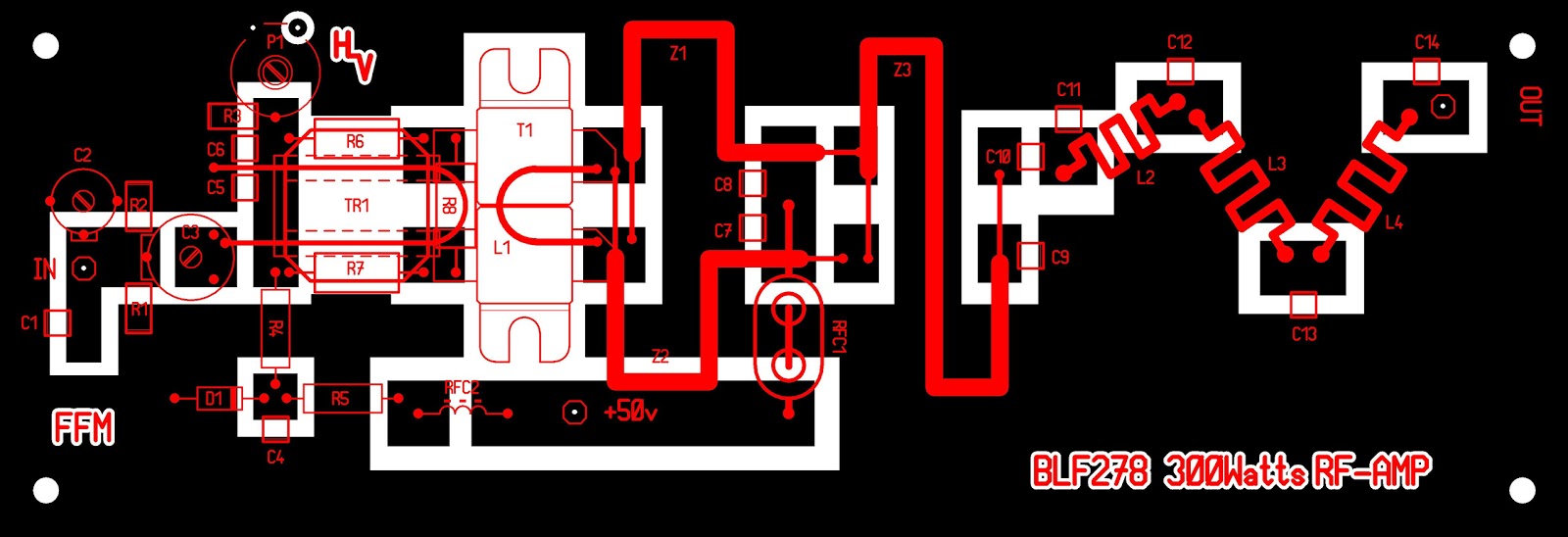
BLF278 300Watts FM-broadcast (87.5-108MHz) broadband RF-amplifier
==================================================================
Resistors
(values are in Ohms, metalfilm or metaloxide, unless otherwise noted)
R1 = 47 (SMD chip-resistor or similar)
R2 = 47 (SMD chip-resistor or similar)
R3 = 3k9 (SMD chip-resistor or similar)
R4 = 3k9 (1/2 watts
R5 = 1k5 (3 watts)
R6 = 12 (3 watts)
R7 = 12 (3 watts)
R8 = 6.8 (3 watts)
P1 = 2k5, 10 mm DIA., horizontal mount (Piher)
Capacitors
(all chip capacitors are brand ATC, type: 100B unless otherwise noted)
C1 = 27pF
C2 = 22pF trimmer capacitor, green (Philips)
C3 = 65pF trimmer capacitor, yellow (Philips)
C4 = 100nF
C5 = 100nF
C6 = 3.3nF
C7 = 100nF
C8 = 3.3nF
C9 = 1nF (porcelain)
C10 = 1nF (porcelain)
C11 = 22pF (porcelain)
C12 = 47pF (porcelain)
C13 = 47pF (porcelain)
C14 = 22pF (porcelain)
Semiconductors
T1 = BLF278 (Philips)
D1 = 5.1 volts, 1.3 watts zenerdiode
Transformers, coils
TR1 = 1:4 broadband balun transformer
Ferrocube, type: 2865000202 (Philips) with 2 brass tubes.
14 x 14 x 8 mm (corematerial must have an operating frequency less or equal to
200MHz)
Primary 2.5 turns teflon wire (innerwire of 3.3 mm Teflon coax will do)
Secondary two brass tubes soldered at one end together (bias side) and the other
ends are soldered to their resp. gate’s of the BLF278 (see drawing)
L1 = 1/2 turn hairpin aircoil, 26 x 11 mm (height x width), 2 mm AgCu wire diameter
L2 = 3 turns, 10 mm internal diameter, 2 mm AgCU wire, 2 mm wirespacing
L3 = 3 turns, 10 mm internal diameter, 2 mm AgCU wire, 2 mm wirespacing
L4 = 3 turns, 10 mm internal diameter, 2 mm AgCU wire, 2 mm wirespacing
Z1 = 50-Ohms Teflon coax, 2.3 mm DIA., 22.5 cm in length
Z2 = 50-Ohms Teflon coax, 2.3 mm DIA., 22.5 cm in length
Z3 = 50-Ohms Teflon coax, 3.3 mm DIA., 24 cm in length
RFC1 = rf-choke, 2-hole ferroxcube core (i.e. balun-core) with 1/2 turn, 2 mm CuL blank
wire through it
RFC2 = VK200-19/4B broadband choke
Notes
AgCu = silver plated copper wire
CuL = magnetwire, enameled copper wire, insulated (rigid) copper wire e.t.c.
(Note: 2 mm equals approx. to #12 A.W.G
1 mm equals approx. to #18 A.W.G
1.2 mm equals approx. to #17 A.W.G
0.8 mm equals approx. to #20 A.W.G
0.3 mm equals approx. to #28 A.W.G.)
(I) all diameters are measured from the inside of the coils, i.e. ‘internal’ diameter.
(II) make sure to mount the rf-transistor on a appropriate heatsink and use some thermal
heatsink compound between the flange of the transistor and heatsink!
(Thermal resistance heatsink at least 6°C/W.)
(III) all parts are soldered directly on the toplayer of the pcb.
(IV) bias is approx. 1.4 volts

0 komentar:
Posting Komentar