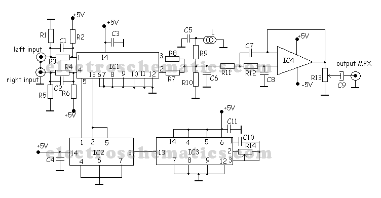
R1 = R5 = 10K
R2 = R6 = 220K
R3 = R4 = R9 = 47K
R7 = R8 = 4.7K
R10 = 68K
R11 = R12 = 27K
R13 = 2.2K variable
R14 = 20K liniar
C1 = C2 = 1nF
C3 = C4 = C11 = 100nF
C5 = C10 = 10nF
C6 = 470pF
C7 = 100pF
C8 = 68pF
C9 = 10uF
L = 6.8mH
IC1 = 4066
IC2 = 4013
IC3 = 4047
IC4 = 741
To adjust the frequency rotate R13 (multiturn) untill on IC2 pin 10 you measure 19kHz or the stereo led lights up on your stereo receiver. From R10 adjust the pilot tone signal and from R7 adjust the sound level. Use metallic resistors and 100nF ceramic capacitor for low noise stereo signal.
If your audio source has dc voltage on audio output connect 2 x 0.47uF capacitor on the stereo encoder inputs. You can use a better T1 like BC549C if you want a higher sound amplification. Keep short circuits distances.
If you want the best from this mpx stereo encoder use metallic resistors, ceramic capacitor, shielded audio cables for input and MPX output and a good stabilized, filtered 5V power supply.
I’ve worked with this stereo encoder in my youth and it’s pretty good, has a 70% stereo separation.
Stereo Encoder circuit components:
R1 = R2 = 68K
R3 = R4 = 270K
R5 = 22K
R6 = 2.2K
R7 = 50K
R8 = R12 = R14 = 10K
R9 = 12K
R10 = 10K variable
R11 = 47K
R13 = 50K variable
C1 = C2 = C7 = C8 = 1nF
C3 = C4 = C5 = C9 = C10 = C12 = 100nF ceramic
C6 = 10uF
C11 = 620pF
IC1 = MMC4066E
IC2 = MMC4047
T1 = BC547B, BC549C
here are 14 possible transmission frequencies with 200KHz increments selected with a 4-DIP switch. Starts from 88.7 up to 89.9 MHz and 107.7 up to 108.9 MHz.
S4 | S3 | S2 | S1 | Frequency |
1 | 1 | 1 | 1 | 88.7 MHz |
1 | 1 | 1 | 0 | 88.9 MHz |
1 | 1 | 0 | 1 | 89.1 MHz |
1 | 1 | 0 | 0 | 89.3 MHz |
1 | 0 | 1 | 1 | 89.5 MHz |
1 | 0 | 1 | 0 | 89.7 MHz |
1 | 0 | 0 | 1 | 89.9 MHz |
1 = ON, 0 = OFF | ||||
Simply select transmission frequency at which you would like to transmit, set the combination for 4-DIP switch and BH1417 will tune to that frequency. If you can’t hear the transmitted audio signal on your FM receiver then re-adjust 2.5 turn variable coil until you can hear the signal.
Technical Specifications:
Supply Voltage: 4 – 6V
Transmission Frequency: 87.7 – 88.9MHz, 106.7 – 107.9MHz (200kHz steps)
Output RF Power: 20mW
Audio Frequency: 20 – 15KHz
Separation: 40dB
Power Consumption: 30mA
Components:
1x BH1417 – Stereo PLL Transmitter IC (Case SOP22)
1x 7.68 MHz Crystal
1x MPSA13 – NPN Darlington Transistor
1x 2.5 Turns Variable Coil
1x MV2109 – Varicap Diode
1x 4-DIP Switch
ANT – 30 cm of copper wire
1x 22K Resistor
7x 10K Resistor
1x 5.1K Resistor
2x 3.3K Resistor
1x 100 Ohm Resistor 1x 100uF Capacitor
3x 10uF Capacitor
2x 1uF Capacitor
7x 10K Resistor
1x 5.1K Resistor
2x 3.3K Resistor
1x 100 Ohm Resistor 1x 100uF Capacitor
3x 10uF Capacitor
2x 1uF Capacitor
1x 47nF Capacitor
3x 2.2nF Capacitor
1x 1nF Capacitor
1x 330pF Capacitor
2x 150pF Capacitor
1x 33pF Capacitor
2x 27pF Capacitor
1x 22pF Capacitor
2x 10pF Capacitor
3x 2.2nF Capacitor
1x 1nF Capacitor
1x 330pF Capacitor
2x 150pF Capacitor
1x 33pF Capacitor
2x 27pF Capacitor
1x 22pF Capacitor
2x 10pF Capacitor
| ||||||||||


0 komentar:
Posting Komentar